|
|
     aHR0cDovL2ZyZWVzaGlwLmNvLmty aHR0cDovL2ZyZWVzaGlwLmNvLmty
- APP 지원: 아니다
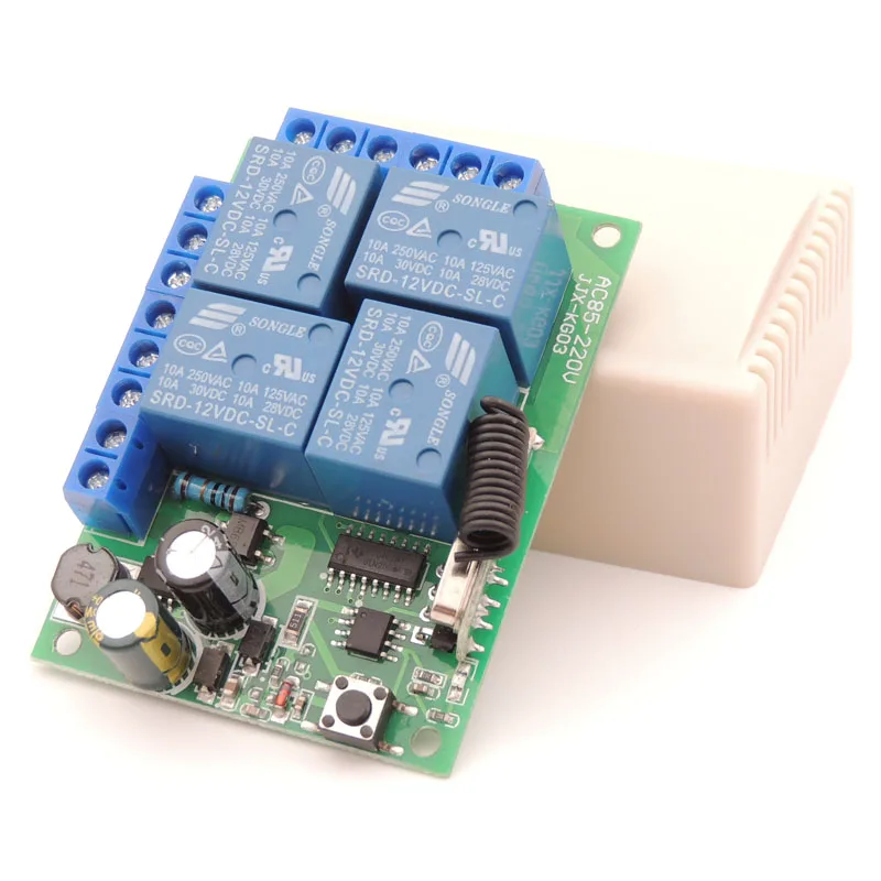
- 주파수: 433 MHz
- 채널: 4
- 포장: 그렇습니다
- 모델 번호: 220404D remote control for gate universal garage door remote control
- 무선 통신: RF
- 사용: 보편,조명,전기 문,자동 커튼,SWITCH
- 브랜드 이름: Diese
- 원산지: 중국
- Working Voltage: 85V~250V
- Input Voltage: 1V~220V
- Output Voltage: 1V~220V
- Quiescent Current: 5mA
- Receiving Sensitivity: 97dbm
- Working temperature: -30~+80
- Shell: Yes
- PCB dimension: 68*47*26(mm)
- RF working mode: superheterodyne
- Output Terminal: NO , NC , COM
- Application Example 1: Mando a Distancia,Garage Door, Electronic Gates, Electrical Appliances
- Application Example 2: Telecomando cancello universale
- Modulation Mode: ASK
- Matching Mode: Intelligent Learning code
- Max Current: 10 Amp
- Max Load: 2200W
옵션정보[(29)1 Remote Control] [(193)1 Receiver 1 RC] [(193)1 Receiver 1 RC] [(691)1 Receiver 2 RC] [(691)1 Receiver 2 RC] [(175)1 Receiver 3 RC] [(175)1 Receiver 3 RC] [(4)1 Receiver 5 RC] [(4)1 Receiver 5 RC]


433MHz Universal Wireless Remote Control AC 110V 220V 10Amp 2200W 4CH Relay Receiver Module RF Switch for Gate Garage opener
*** Tips:If you need us to set up the operating mode , please leave a message on the order ***
Product Application Area
Remote control garage door \ Remote control house door \ Remote control Lamp \ Remote control curtains \ Remote control Gate and other remote control device

Package include
Receiver module( include Shell )
Remote Control (include battery )
Product manual


Technical Data
Electronics Character:
Working Voltage:AC 85V~250V Input Voltage:1V~250V Output Voltage:1V~250V Max current : 10Amp max load: 2200W Quiescent Current:5mA Working Frequency:433Mhz Receiving Sensitivity:-104dBm Function option:Momentary/Toggle/Latched Modulation Mode:ASK Matching Mode: Intelligent Learning code Output Mode:Dry contact /Voltage output Shell:Yes Working temperature : -30~+80 PCB dimension:68.2x48.2(mm)
Pin functions:
+V :Positive pole input GND :Negative pole input
Relay 1/2/3/4
Products Display
Tips:
All of our products are of high quality!
If you have other needs, please feel free to purchase them in our store.
Circuit Connection modes
Please Note:
the Receiver Switch Module have 3 ways of working mode.The OUTPUT signal has 2 Voltage Level. It decided by the INPUT of the COM pin.
  

NOTES
1. Please do not charged operation, you should shut off the power, and operation after testing and correct electricity.
2. Please promptly change battery when remote control voltage is insufficient, (when the battery voltage is insufficient, generally get close transmitting )
3. Please pay attention to avoid metal mask,large equipment ,strong interference electromagnetic filed when using wireless RF products,and avoid too short distance between the remote control and receiver board .
4. Please avoid abnormal using of the product.Abnormal using will reduce product performance and life, when seriously it may damage the products and even make danger for your safe .
Operating Mode
You can match the Remote Control with the Receiver Switch Module in 3 modes.
Press and hold on one button -> ON; Release the button -> OFF
Details:
Press one button (on the remote control), the relay (on the receiver board) turn to
switch-on
;
Release the button, the relay turn to
switch-off
.
Press one button -> ON; Press the same button again -> OFF
Details:
Press one button (on the remote control) once, the relay (on the receiver board) turn to
switch-on
;
Press the same button again, the relay turn to
switch-off.
Press one button "A"-> ON; Press another button "B" -> OFF(another relay turn to switch-on)
Details:
Press one button "A"(on the remote control) once, one relay (on the receiver board) turn to
switch-on
;
Press anotherbutton "B"
once
, the relay turn to
switch-off(At the same time another relay turn to switch-on
)
Set Up
- Part 1: Delete the existing data about remote mode
Note:
When you receive our products, it maybe set in one remote mode randomly, that because each product got test when it can be arranged to shipment.So, please delete the existing data about remote mode for the first application.
Press the learning button on the
Receiver Switch Module board
8 times
,
the existing data are deleted successfully.
After deleted the data, all the remote control cannot work any more.

- Part 2: Set up the Remote Mode
Remote mode 1: Momentary Mode
Press and release the learning button on the
Receiver Switch Module board
once.
Wait for a moment , the LED will turn off , indicating you entered the learning state.
Press and release one button on the
Remote Control
, the LED on the receiver board will flash on then off indicating the button was learned.
Wait 3 seconds, the LED will turn on again, indicating system is ready for use.
Remote mode 2 :
Toggle Mode
Press and release the learning button on the
Receiver Switch Module board
twice.
Wait for a moment , the LED will turn off , indicating you entered the learning state.
Press and release one button
on the
Remote Control
, the LED on the receiver board will flash on then turn off , indicating the button was learned.
Wait 3 seconds, the LED indicator will turn on again , indicating system is ready for use.
Remote mode 3 : Latched Mode
Press and release the learning button on the
Receiver Switch Module board
triple.
Wait for a moment , the LED will turn off , indicating you entered the learning state.
Press and release one button
on the
Remote Control
,
the on-board LED indicator will flash 5 times to inform that the setting of latched mode successful .
Wait 3 seconds, the LED indicator will turn on again , indicating system is ready for use.
On this products details page, there is a demonstration video available.
*If you do not understand clearly. Please send us a message to let us know. We will do our best to service each of our customers. Enjoy your shopping!*


|
|
|
|
|


 배송기간
배송기간