플레이스 홀더
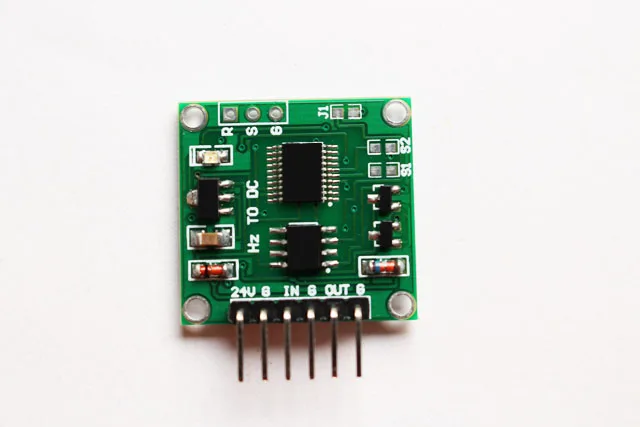
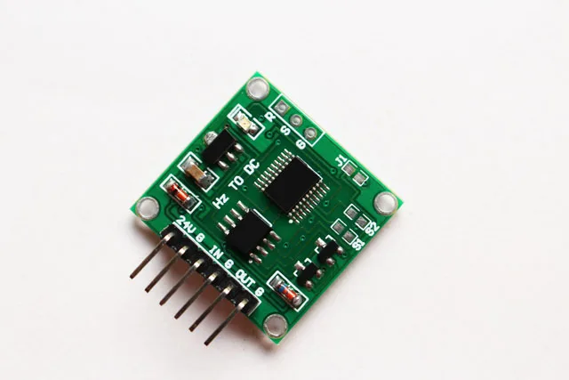
Frequency to Voltage Module
This is a linear conversion module, which converts the input frequency signal to the standard voltage signal output through the internal chip processing.
There are two kinds of output voltage range choices.
Modular parameters
1. Power supply voltage: 9V-24V
2. Signal input voltage range: 4-24V
3. Signal input frequency range: 0Hz-10KHz
4. Signal Input Duty Ratio Range: 5-95%
5. Output Voltage: 0.00V-5.00V/0.00V-10.00V
6. Input mode: S1 pad on circuit board: default is open input 0-10kHz, short-circuit input 0-1kHz.
7. Output mode: S2 pad on circuit board: open circuit (output 0.00V-5.00V); short connection (output 0.00V-10.00V), default is open circuit.
8. Scope of application: remote data acquisition and control equipment;
9. Dimensions: (long) 26mm * (wide) 23mm * (high) 10mm
10. Modular interface:
12V: POWER POSITIVE INTERFACE (9V~24V).
G: Power ground interface.
IN: Signal input positive interface.
G: Signal input negative interface.
OUT: Output interface of signal (0.00V-5.00V/0.00V-10.00V).
G: Power ground interface.
Note: When the output is 0.00V to 10.00V, the power supply voltage should be 15 volts.
Output (0.00V-5.00V) resolution: 0.0005V/D (volt/hertz)
Output (0.00V-10.00V) resolution: 0.0010V/D (volt/hertz)
The formula for calculating the measured frequency ratio is (output voltage (V)/resolution) = frequency (Hertz).
For example, the output (0.00V-5.00V) is 2.5V.
(2.5 (V)/0.05) = 5000 (Hz).


 배송기간
배송기간